Draw communication diagrams to simplify UML sequences
Communication diagrams (formerly collaboration diagrams) show the messages that are passed in a system as an action is taken or an event occurs, and in what order they are sent. As a simplified sequence diagram, these show the information sharing relationships more clearly between different elements of a system.
You can use these diagrams to debug communications problems and simplify processes in software applications, in real-life processes where teams and departments work together, or in industrial settings such as where machines on a factory floor need to communicate with a central monitoring station.
Communication diagrams can also be used to clearly document processes that need to be audited for information security accreditations.
Why draw both communication and sequence diagrams?
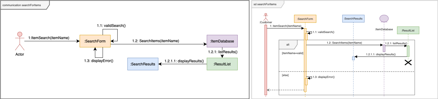
Where it is easier to read the order of interactions in a sequence diagram, communication diagrams show which system elements are involved more clearly.
Communication diagrams are often drawn after sequence diagrams have been finalised for audit documentation, or to present to leaders to show communications requirements for systems and processes.
How to read the diagram
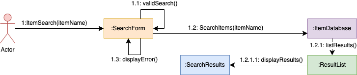
Communication diagrams may be drawn from left to right or top to bottom, however, you always read the diagram starting with message 1.0.
Shapes in a communication diagram
The shapes used in these diagrams are simple, and available in the General shape library in draw.io.
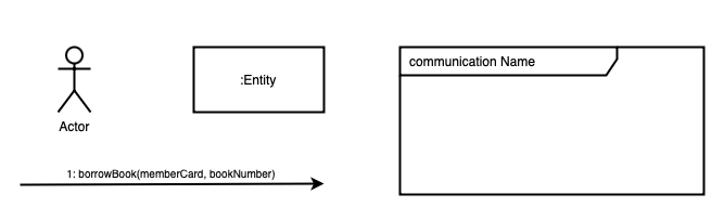
Actor: is the person or system that initiates the sequence.
Entity (rectangle): shows the elements of a system that are interacted with to achieve the goal of the action. These are usually preceded by a colon :. These rectangles represent the various lifelines the matching sequence diagram.
Message (connector): are connectors with arrows at one end to show the direction in which messages are passed, and a label with the numbered sequence step.
Frame: an optional shape in the UML and UML2.5 shape libraries which can be used to surround a communication diagram. The frame title should include the diagram type communication followed by name of the action or event.
Numbering the message sequence
Connector labels in communication diagrams always show the message sequence number and usually look like function calls which may contain variables - information passed to the receiving element. They need to be numbered carefully.
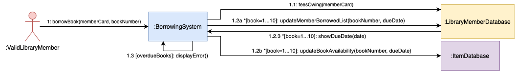
When two or more messages are passed at the same time to different entities, they will have the same number, but an additional letter - 1.1a and 1.1b are two messages sent at the same time (concurrent activation). For example, when a person has returned a book to the library, their list of borrowed books must be updated in the user database, and the book availability needs to be changed in the library database, at the same time.
Conditions or ‘guards’ are added to message labels in square brackets. For example, if a person wants to borrow more than one book, but there is a limit of 10 books, 1.1b *[book=1...10]: CheckOut(book) will check out one book, 10 times in a row.
While there are additional notation options for loops (*|| and *) described in the UML 2.5 specification, these can make your communication diagram harder for non-UML experts to read and are better shown in a sequence diagram.
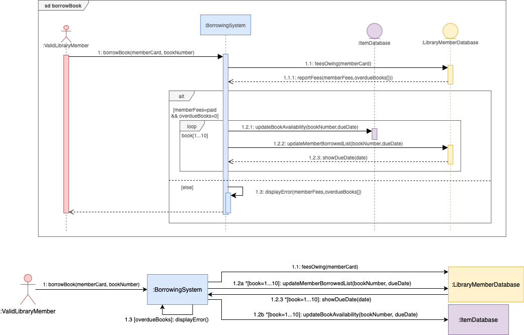
In the example below, you can see how the more complex sequence diagram for a library user who borrows between 1 and 10 books is converted into a communications diagram. The message sequence labels include concurrent repeating messages to both the user database and the library’s book database.
More UML diagrams
Communication diagrams are one of four interaction diagrams in the UML specification. Refer to the UML diagram overview post for the many other types of UML diagrams and how to draw them in draw.io.
